
Choosing a wafer dicing saw for 8-inch and 12-inch wafers requires more than confirming the maximum supported wafer diameter.
An 8-inch wafer is generally referred to as a 200 mm wafer, while a 12-inch wafer is commonly specified as a 300 mm wafer. Although both can be processed by precision blade dicing equipment, they have different requirements for machine travel, frame handling, spindle configuration, automation, cleaning and production throughput.
The correct machine should match the wafer material, thickness, dicing street, edge-quality requirement and production volume. Selecting equipment only according to wafer size may lead to insufficient accuracy, low throughput, excessive chipping or unnecessary investment.
This guide explains the main factors buyers should evaluate when selecting a wafer dicing saw for 200 mm and 300 mm wafers.
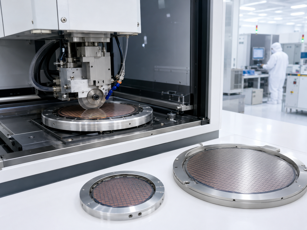
8-Inch vs 12-Inch Wafer Dicing Saw
| Selection factor | 8-inch wafer | 12-inch wafer |
|---|---|---|
| Nominal diameter | 200 มิลลิเมตร | 300 มิลลิเมตร |
| Typical processing mode | Semi-automatic or fully automatic | Usually fully automatic for volume production |
| Equipment footprint | Relatively compact | Larger cutting and handling platform |
| Common spindle configuration | Single or dual spindle | Single or dual spindle |
| Handling requirements | Manual frame loading or automatic cassette handling | Automatic frame or cassette handling often preferred |
| Production applications | R&D, MEMS, sensors, power devices, compound semiconductors and packaging | Logic, memory, advanced packaging and high-volume semiconductor production |
| Main purchasing concern | Flexibility and cost efficiency | Throughput, handling stability and automation |
| Capital investment | Generally lower | Generally higher |
A 12-inch system normally requires a larger chuck table, longer motion travel and more robust handling equipment. However, wafer size should not be the only reason to select a larger or more expensive machine.
The buyer should first define the actual processing requirements.
1. Confirm the Wafer and Dicing Frame Dimensions
The machine must accommodate the complete mounted workpiece, not only the wafer itself.
Important dimensions include:
- Wafer diameter
- Wafer thickness
- Dicing-frame outer diameter
- Tape size
- Frame thickness
- Wafer mounting position
- Edge clearance
- Number of substrates mounted on one frame
- Maximum wafer bow and warp
A 200 mm wafer mounted on a dicing frame requires a cutting table larger than 200 mm. A 300 mm wafer also requires additional space for frame support, alignment and edge cutting.
Before selecting a machine, confirm:
- Maximum workpiece diameter
- Chuck-table diameter
- X-axis cutting range
- Y-axis indexing range
- Frame-loader compatibility
- Maximum substrate thickness
- Maximum permitted bow and warp
- Clearance between the workpiece and spindle assembly
The machine should have enough travel to complete all edge cuts without operating at the extreme limit of the motion platform.
2. Select the Appropriate Automation Level
Wafer dicing saws are generally available in manual, semi-automatic and fully automatic configurations.
Semi-automatic wafer dicing saw
A semi-automatic machine normally requires the operator to load and unload the wafer frame. Alignment, indexing and cutting are then controlled by the machine.
It is suitable for:
- Research laboratories
- Process development
- Prototype production
- Small production batches
- Frequent product changes
- Multiple wafer materials
- Custom substrate cutting
- Pilot manufacturing lines
The main advantages are:
- Lower equipment investment
- Smaller footprint
- Flexible recipe changes
- Easier maintenance
- Suitable for different wafer and substrate types
A semi-automatic system may be sufficient when daily production volume is limited and operator loading does not create a bottleneck.
Fully automatic wafer dicing saw
A fully automatic system may integrate:
- Cassette loading
- Wafer-frame transfer
- Automatic pre-alignment
- Pattern recognition
- Automatic cutting
- Kerf inspection
- Wafer cleaning
- Spin drying
- Automatic unloading
- Recipe management
- Production-data recording
It is more suitable for:
- High-volume semiconductor manufacturing
- Continuous production
- Strict traceability requirements
- Limited manual handling
- Stable processing between production shifts
- Factory automation integration
For 300 mm wafer production, full automation is often preferred because the larger wafer and frame are more difficult to handle manually and have a higher material value.
However, full automation is not always necessary. A semi-automatic 300 mm machine may still be suitable for process development, sampling and low-volume production.
3. Choose Between Single-Spindle and Dual-Spindle Systems
The number of spindles affects throughput, process flexibility, machine price and maintenance requirements.
Single-spindle dicing saw
A single-spindle system uses one blade to complete the cutting process.
It is commonly used for:
- Laboratory applications
- Low-volume production
- Standard silicon wafer dicing
- Thick substrate cutting
- Frequent blade changes
- Multiple material types
- Custom cutting projects
Main advantages include:
- Lower purchase cost
- Simpler machine structure
- Easier process setup
- Lower maintenance requirements
- Greater flexibility for changing applications
A single-spindle machine may be the more economical choice when cutting time is not the main production bottleneck.
Dual-spindle dicing saw
A dual-spindle system uses two spindles to increase productivity or perform multi-step cutting.
Possible applications include:
- Simultaneous cutting
- Step cutting
- Two-pass cutting
- Different blade specifications
- Package singulation
- High-volume production
- Reduced wafer cycle time
A dual-spindle system is more suitable when:
- The wafer contains many cutting streets
- Production volume is high
- Cycle time directly affects manufacturing capacity
- Two different blade types are required
- Step cutting is part of the process
The buyer should compare the cycle-time reduction with the additional cost of the second spindle, control system, blade setup and maintenance.
4. Match the Spindle to the Wafer Material
Different wafer materials create different cutting loads.
Common materials include:
- ซิลิคอน
- ซิลิคอนคาร์ไบด์
- แซฟไฟร์
- Gallium arsenide
- Gallium nitride
- Glass
- Fused silica
- ควอตซ์
- Alumina ceramic
- Aluminum nitride
- LTCC
- Molded semiconductor packages
- Composite substrates
Standard silicon wafers can often be diced using high-speed spindles and thin diamond blades.
Hard or brittle materials may require:
- Higher spindle torque
- Greater spindle rigidity
- Lower cutting speed
- Specialized diamond blades
- Controlled blade exposure
- Improved cooling
- Frequent blade dressing
- Stable workpiece support
- More effective debris removal
Important spindle specifications include:
- Spindle power
- Spindle torque
- Rotation-speed range
- Radial runout
- Blade diameter
- Blade flange type
- Cooling method
- Maximum cutting load
- Blade-breakage detection
A high-speed spindle is not automatically better than a high-torque spindle.
For thin silicon wafers, high rotational speed may help support a narrow kerf and thin blade. For thick ceramics, glass or hard compound semiconductor materials, spindle torque and rigidity may be more important.
5. Evaluate Positioning Accuracy and Repeatability
Machine accuracy should not be judged by a single specification.
Important parameters include:
- X-axis positioning accuracy
- Y-axis indexing accuracy
- Z-axis height accuracy
- Theta-axis rotation accuracy
- Axis repeatability
- Full-travel cumulative error
- Single-pitch error
- Thermal drift
- Spindle runout
For narrow dicing streets, even a small positioning error can damage active die areas, metal structures or seal rings.
The required accuracy depends on:
- Dicing-street width
- Die dimensions
- Blade thickness
- Required kerf width
- Wafer pattern
- Alignment-mark quality
- Maximum permitted edge damage
The supplier should demonstrate actual cutting results rather than relying only on motion-system specifications.
Recommended acceptance measurements include:
- Cut-position deviation
- Kerf-width variation
- Front-side chipping
- Back-side chipping
- Cut-depth variation
- Corner damage
- Blade marks
- Burrs
- Delamination
- Repeatability across multiple wafers
A machine with high positioning resolution can still produce poor results if the spindle, blade, coolant or mounting process is unstable.
6. Define the Dicing Street and Kerf Width
The dicing street is the space between adjacent dies where the blade performs the cut.
The buyer should provide:
- Dicing-street width
- Blade thickness
- Target kerf width
- Maximum cut-position deviation
- Distance between the cut and active die area
- Seal-ring position
- Metal-test structure position
- Passivation-layer condition
- Maximum permitted chipping
The actual kerf is normally wider than the nominal blade thickness.
Kerf width can be affected by:
- Blade vibration
- Spindle runout
- การสึกหรอของใบมีด
- Feed speed
- Cutting depth
- Material hardness
- Coolant flow
- Blade dressing condition
For narrow-street wafers, the machine should provide:
- High-resolution vision alignment
- Stable indexing accuracy
- Automatic theta correction
- Kerf inspection
- Cut-position compensation
- Thin-blade compatibility
Actual kerf width should be measured during sample cutting.
7. Compare Real Production Throughput
Maximum cutting speed does not represent actual production capacity.
The total wafer cycle time may include:
- Wafer loading
- Frame recognition
- Pre-alignment
- Pattern recognition
- First-direction cutting
- Wafer rotation
- Second-direction cutting
- Kerf inspection
- Wafer cleaning
- Spin drying
- Wafer unloading
Actual throughput depends on:
- Wafer diameter
- Number of dicing streets
- Die size
- Feed speed
- Number of cutting passes
- Alignment time
- Cleaning time
- Blade-change frequency
- Recipe-change frequency
- Operator handling
- Inspection requirements
A 12-inch wafer contains a larger processing area than an 8-inch wafer. However, the final cycle time also depends on die dimensions and cut pitch.
When comparing equipment, ask the supplier to provide:
- Estimated cycle time per wafer
- Wafers per hour
- Wafers per shift
- Cutting time
- Non-cutting time
- Cleaning and drying time
- Blade-change downtime
- Expected equipment utilization
Throughput estimates should be based on the buyer’s actual wafer map and dicing pattern.
8. Check Thin-Wafer and Warped-Wafer Capability
Thin wafers require careful handling during mounting, cutting, cleaning and unloading.
Potential problems include:
- การแตกร้าวของเวเฟอร์
- การเปลี่ยนรูปของเทป
- Edge lifting
- Vacuum instability
- Wafer vibration
- Die movement
- Backside chipping
- Water penetration
- Broken dies during unloading
The supplier should confirm:
- Minimum supported wafer thickness
- Maximum permitted wafer bow
- Maximum permitted wafer warp
- Recommended dicing tape
- Frame-stiffness requirement
- Chuck-table vacuum zoning
- Wafer-breakage detection
- Low-pressure cleaning capability
- Compatibility with temporary bonding
- Compatibility with dicing-before-grinding processes
For ultra-thin wafers, the complete process should be tested from wafer loading through final cleaning and unloading.
Cutting quality alone is not enough if the wafer breaks during handling.
9. Evaluate the Vision and Alignment System
The alignment system must recognize the actual wafer pattern under production conditions.
Important functions include:
- Manual alignment
- Automatic dicing-street recognition
- Pattern matching
- Multiple alignment points
- Automatic theta correction
- Low-contrast pattern recognition
- Backside alignment
- Infrared alignment
- Wafer-map integration
- Kerf inspection
- Automatic cut-position correction
Patterned semiconductor wafers normally require a more advanced vision system than blank glass, quartz or ceramic substrates.
Before purchasing the machine, provide representative images or sample wafers showing:
- Alignment marks
- Dicing streets
- Reflective metal layers
- Protective coatings
- Low-contrast patterns
- Different wafer orientations
- Edge exclusion areas
The supplier should verify that the vision system can consistently identify the cutting streets.
10. Review Wafer Cleaning and Drying
Blade dicing uses water to cool the blade and remove cutting debris.
After dicing, the wafer may need:
- Rinsing
- Particle removal
- Low-pressure cleaning
- Two-fluid cleaning
- CO₂-added water
- Spin rinsing
- Spin drying
- Corrosion control
- Watermark prevention
Cleaning requirements depend on the wafer structure.
Special attention may be required for:
- MEMS wafers
- Wafers with cavities
- Exposed metal layers
- Fragile dies
- Optical devices
- Porous materials
- Bonded wafers
- Devices sensitive to water pressure
The cleaning unit may be integrated into the dicing saw or installed as separate equipment.
An integrated system reduces manual handling. A separate cleaning system may provide greater process flexibility.
11. Consider Blade and Consumable Availability
The machine should support blades that are readily available for the intended material and kerf requirement.
Consumables may include:
- Diamond dicing blades
- Blade flanges
- Dicing tape
- Wafer frames
- Dressing boards
- Water filters
- Nozzles
- Cleaning chemicals
- Coolant additives
Before purchasing equipment, confirm:
- Supported blade diameter
- Supported blade thickness
- Maximum blade exposure
- Blade-flange dimensions
- Compatible tape-frame sizes
- Blade availability
- Consumable lead time
- Blade-life monitoring
- Automatic blade setup
- Blade-breakage detection
A machine may have a competitive purchase price but become expensive to operate if the required blades and spare parts are difficult to obtain.
12. Compare Equipment Footprint and Factory Requirements
A 300 mm dicing system normally requires more floor space and utility capacity than a 200 mm system.
Factory requirements may include:
- Electrical power
- Compressed air
- Vacuum
- Exhaust
- Deionized water
- Water chiller
- Drainage
- CO₂ supply
- Cleanroom space
- Temperature control
- Vibration control
- Network connection
The quotation should clearly state which peripheral systems are included.
Possible additional equipment includes:
- Water chiller
- Filtration system
- CO₂ injection unit
- Tape-mounting machine
- Wafer cleaning system
- Wafer inspection equipment
- Blade-dressing equipment
- Frame storage system
These items should be included in the total investment calculation.
13. Calculate the Total Cost of Ownership
The machine purchase price is only one part of the total cost.
Buyers should calculate:
Initial investment
- Equipment price
- Optional functions
- Shipping
- Insurance
- Import duties
- Installation
- Calibration
- Training
- Factory acceptance testing
- Site acceptance testing
Facility cost
- Electrical installation
- Water system
- Chiller
- Compressed air
- Vacuum
- Exhaust
- Drainage
- Cleanroom modification
Operating cost
- Dicing blades
- Dicing tape
- Water filters
- Cleaning materials
- Electricity
- Deionized water
- Labor
- Preventive maintenance
- Spare parts
Process-related cost
- Broken wafers
- ขอบแตก
- Blade breakage
- Equipment downtime
- Recipe-development wafers
- Qualification samples
- Yield loss
- Production delays
A lower-priced machine may have a higher total cost if it creates more downtime, consumes more blades or produces unstable dicing quality.
14. When to Choose an 8-Inch Dicing Saw
An 8-inch system may be the better choice when:
- The maximum wafer diameter is 200 mm
- The factory mainly processes 100–200 mm wafers
- Production volume is moderate
- Floor space is limited
- Frequent process changes are required
- Multiple substrate materials are processed
- The project is in R&D or pilot production
- Lower equipment investment is important
A 200 mm system can provide a good balance between capability, flexibility and cost.
15. When to Choose a 12-Inch Dicing Saw
A 12-inch system may be necessary when:
- The product uses 300 mm wafers
- Future production will move to 300 mm
- High-volume manufacturing is planned
- Automatic wafer handling is required
- Factory integration is required
- Manual handling must be minimized
- Production traceability is required
- Large wafer-frame compatibility is essential
A 300 mm system can sometimes process smaller wafers with suitable fixtures and recipes. However, this should be confirmed with the supplier.
Purchasing a 300 mm machine only for possible future demand may not be economical when current production is limited to 200 mm wafers.
Wafer Dicing Saw RFQ Checklist
Provide the following information when requesting a machine quotation.
Wafer information
- Wafer material
- Wafer diameter
- Wafer thickness
- Surface condition
- Wafer bow and warp
- Patterned or unpatterned
- Frame dimensions
- Dicing-tape type
Cutting requirements
- Die dimensions
- Dicing-street width
- Blade thickness
- Required kerf width
- Full cut or half cut
- Cut depth
- Number of passes
- Maximum front-side chipping
- Maximum back-side chipping
- Cut-position tolerance
Production requirements
- Wafers per hour
- Wafers per day
- Number of product types
- Frequency of recipe changes
- Required automation level
- Single- or dual-spindle preference
- Loading and unloading method
- Cleaning and drying requirements
Quality requirements
- ความแม่นยำในการจัดแนว
- Kerf inspection
- Die-strength requirement
- Particle requirement
- Traceability
- Production-data recording
- Acceptance-test standard
Sample Cutting and Machine Acceptance
Before final machine selection, buyers should request a cutting trial using actual wafers or representative substrates.
The trial should use:
- Actual wafer material
- Actual wafer thickness
- Actual dicing tape
- Target blade specification
- Required feed speed
- Actual dicing-street width
- Actual cleaning process
Inspect the samples for:
- Cut-position accuracy
- Kerf width
- Front-side chipping
- Back-side chipping
- Corner damage
- Delamination
- Burrs
- Cracks
- Surface contamination
- Die strength
The purchase agreement should include measurable acceptance criteria.
คำถามที่พบบ่อย
Can one dicing saw process both 8-inch and 12-inch wafers?
Some 300 mm systems can process smaller wafers by using appropriate chuck tables, adapters, frames and recipes. Compatibility should be confirmed before purchase.
Is a 12-inch dicing saw more accurate than an 8-inch saw?
Not necessarily. Accuracy depends on the machine design, spindle stability, motion control, alignment system and process setup. Wafer capacity alone does not determine accuracy.
Is a dual-spindle system necessary for 300 mm wafers?
No. A single-spindle system may be suitable for R&D, sampling and low-volume production. Dual spindles are mainly used to increase throughput or support multi-step cutting.
What is the most important machine specification?
There is no single most important specification. Buyers should evaluate positioning accuracy, spindle performance, alignment, chipping, kerf stability, throughput and wafer-handling reliability together.
Can the same machine dice silicon, SiC, sapphire and glass?
A machine may support multiple materials, but each material requires different blades, spindle settings, cooling conditions, dressing methods and feed speeds. Sample testing is recommended.
How should buyers compare dicing-saw quotations?
Compare the complete installed configuration, including the spindle, vision system, automation, cleaning, peripherals, installation, training, warranty and acceptance testing.
Should a laboratory purchase a fully automatic system?
A fully automatic system may be unnecessary when production volume is low and products change frequently. A semi-automatic machine may provide better flexibility and lower total cost.
What information is needed for an accurate quotation?
The supplier needs the wafer material, diameter, thickness, frame size, dicing-street width, required kerf, maximum chipping, production volume and automation requirements.
สรุป
Choosing a wafer dicing saw for 8-inch or 12-inch wafers requires a complete evaluation of the process.
An 8-inch machine is often suitable for flexible production, compound semiconductor wafers, MEMS, sensors, R&D and moderate manufacturing volumes. A 12-inch system is generally selected for 300 mm wafer processing, high-volume production and automated factory integration.
The final decision should be based on:
- Wafer size and frame dimensions
- Material and thickness
- Dicing-street width
- Required kerf and chipping
- Spindle power and torque
- Positioning accuracy
- Automation level
- Cleaning requirements
- Production throughput
- Total cost of ownership
Before requesting a quotation, prepare the wafer drawing, material information, thickness, cutting layout, tolerance requirements and production target. Sample cutting should be completed before the machine configuration is finalized.